Drawing Conventions Explained
Orthographic -
ORTHOGRAPHIC DRAWINGS
Three views are usually shown:
The most detailed Front Elevation
( A in this sketch )
The End Elevation
( D in this sketch )
The Plan - the view from ‘above’
( B in this sketch )
Three views are usually shown:
The most detailed Front Elevation
( A in this sketch )
The End Elevation
( D in this sketch )
The Plan -
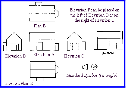
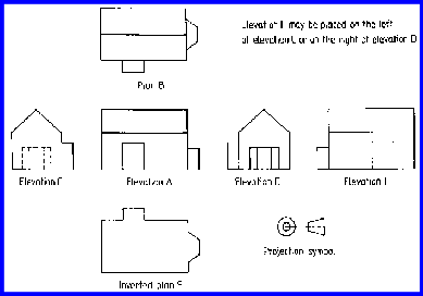
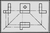
You should try to draw using the ‘ 3rd Angle ’ convention as seen in this drawing ~
Check to see what the difference is between this 3rd angle and the alternative ‘1st Angle’ example.
Check to see what the difference is between this 3rd angle and the alternative ‘1st Angle’ example.
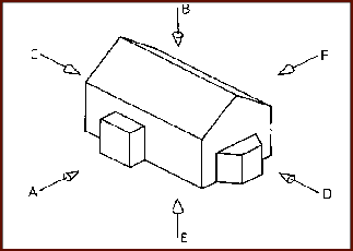
B
F
C
A
D
E
If you look at the two different conventions shown, you should be able to see that the position of one of the end elevation drawings ~ for example the right hand end of Elevation A (shown as drawing ‘D’) has been crossed over to the opposite side of the Front Elevation - (Drawing ‘A’) on the FIRST ANGLE drawing.
On the THIRD ANGLE drawing the view of the end elevation
is drawn together with (i.e. alongside) - the position of that end on the elevation drawing.
( Remember : T Together and T Third Angle )

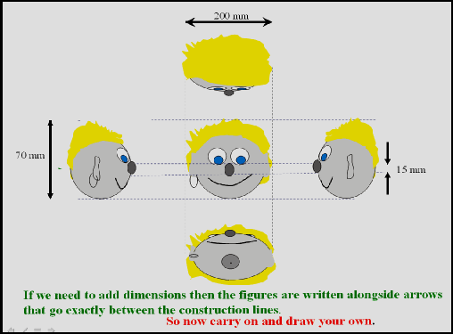

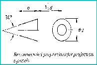
Recommended proportions for projection symbols
Further useful background ‘info’


IF IN DOUBT ASK !
Why donate ?